MIL-PRF-46176B
(1) Determine the base diameter of each cup to the nearest 0.03 mm. Using a
micrometer, make two diametrical measurements at right angles to each other
on each cup. If the two readings differ from each other by more than 0.08 mm,
discard the cup. The base diameter shall be the average of these two
measurements.
(2) Determine the hardness of each cup IAW ASTM D1415.
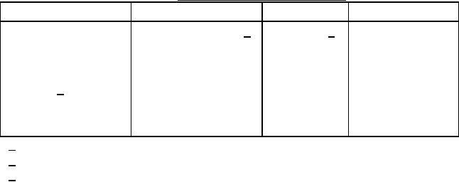
b. Three metal strips of each of the materials listed in table IV are required. Each
strip shall have a surface area of 26 ± 5 cm2, and shall measure 76 mm by 13 mm
by less than 6.4 mm. Each strip shall have a hole, approximately 4.8 mm in
diameter, centered 6.4 mm from one end. Clean all strips, with the exception of
the tinned steel, by abrading them with No. 320A waterproof silicon carbide paper
and 95% ethyl alcohol until all surface scratches, cuts, and pits are removed from
all of the strips. Polish with 00 steel wool. Rinse all of the strips in 95% ethyl
alcohol, dry them with a clean, lint-free cloth, and condition them to constant
weight in a desiccator. Weigh each strip to the nearest 0.1 milligram (mg).
TABLE IV. Corrosiveness test strip materials.
Material
Designation
Temper
Specification
Electrolytic tinned steel Class 25, Type MR 1/
T-5 2/
ASTM A624
Low carbon steel
UNS G10180
4 or 5
SAE J403
Aluminum
Alloy 2024
0
AMS-QQ-A-250/4
Cast iron 3/
Grade G3000
Not applicable
SAE J431
Brass
UNS C26800
H02
ASTM B36
Copper
UNS C11400
H02
ASTM B152
1/ Base weight: 80lb/base box
2/ Continuously annealed
3/ Strips to be cut from brake wheel cylinders
c. Wet the metal strips with the brake fluid under test. Fasten one strip of each of the
metals together through the holes in the strips, using an uncoated cotter pin or a
size No. 6 or 8 uncoated mild steel bolt with nut to ensure electrolytic contact
between the strips. The strips shall be arranged in the same order in which they are
listed in table IV. Bend them so as to make a separation of at least 3 mm between
the adjacent strips for a distance of approximately 60 mm, measured from the free
end of the strips. Place the three sets of assembled strips in separate screw-cap
jars of approximately 473-mL capacity (see 6.4). One SBR wheel cylinder cup
shall also be placed in the container in such a manner that the pinned ends of the
strips rest in, and are in contact with, the concavity of the cup. Prepare a sufficient
amount of humidified brake fluid (see 4.3.6.3), and pour it into each jar to a depth
11
For Parts Inquires call Parts Hangar, Inc (727) 493-0744
© Copyright 2015 Integrated Publishing, Inc.
A Service Disabled Veteran Owned Small Business